
Breadboards: Rows, Rails and the Center Gap
7 min read
BREADBOARDS: ROWS, RAILS AND THE CENTER GAP
A breadboard lets you prototype circuits without soldering. Small spring clips under its holes connect particular groups of holes. The outside can look like a grid, but the connections beneath it follow a pattern.
THE MAIN TERMINAL STRIP
On many boards, each group of five holes in a numbered row is connected together on one side of the center gap. The matching five holes on the other side are a separate group. The center trench isolates the two sides, making it convenient to place dual-inline chips across the gap. Never assume every board is identical: check its markings or test continuity with a meter.
POWER RAILS
Long strips along the edges are often used for positive supply and ground. Some boards split a rail in the middle, so the top and bottom halves may not connect. Use short jumper wires to bridge a split when needed. Red and blue markings are helpful guides, but the colors do not create electrical connections by themselves.
BUILD A SIMPLE LED CIRCUIT
You need a breadboard, a 3–5 V battery pack, one LED, one 330 Ω to 1 kΩ resistor, and jumper wires. Connect battery positive to a rail. Connect that rail through the resistor to the LED anode (the longer leg). Connect the LED cathode (shorter leg, flat edge on the case) to the ground rail. Connect battery negative to ground. The path is: positive → resistor → LED → ground → battery.
BEFORE POWERING ON
Check that the resistor is in series with the LED, the LED polarity is correct, and positive is not connected directly to ground. Start with a low voltage. If the LED stays off, remove power and check each connection one row at a time.
COMMON MISTAKES
Putting both LED legs in the same connected row shorts the LED out of the circuit. Placing a part across the center gap can separate its pins as intended. A wire that looks adjacent may be in a different row. Count rows carefully and consult the board’s connection diagram.
TRY IT
Move the resistor to a different row while keeping both ends connected in the same path. The LED should still light. Then move one end of the resistor to an unconnected row: the circuit should open and the LED should turn off.
SAFETY
Disconnect power before changing wires. Do not use mains voltage on a solderless breadboard. Never place a battery directly across the power rails without a load; that creates a short circuit.
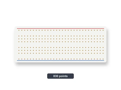
Holes linked by a line are electrically joined under the board. The center gap keeps the two terminal strips separate.