Kids OK with adultESP32Level 3/3
DOG-12 Robot Dog
A 14-servo robot dog that walks, sits, gives a paw, dances and does a little pounce hop.
Sign in to save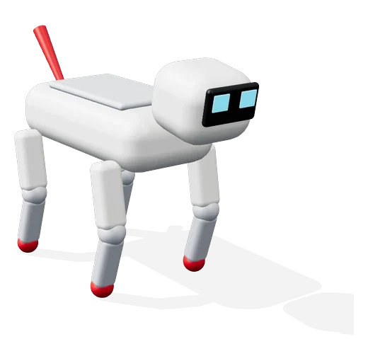
Kids OK, with an adult
DIY project. Children must build this only with an adult (16+ years) beside them at all times. Not suitable for children under 8 years.
An adult handles the Li-ion pack. Never power the servos from the ESP32 or USB 5 V: the board browns out and the legs go limp.
Strictly follow the description given with this video.
Video
How it works
- Each leg has 3 servos (side, hip, knee); the knee is driven by a push-rod from a servo up in the upper leg.
- A 16-channel servo driver gives all 14 servos their signals over I2C.
- The tilt sensor keeps it balanced; the ultrasonic snout sees obstacles; the small screen shows its eyes.
- A 7.4 V pack feeds a 6 V 10 A converter for the servos and a 5 V converter for the ESP32.
Parts you need
 ESP32 dev board₹518× 1Buy
- 16-channel servo driver (I2C)₹345× 1Buy
 14× 20 kg·cm metal-gear servos (6 V)₹1,322× 14Buy
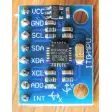 IMU tilt sensor₹172× 1Buy
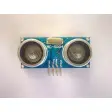 HC-SR04 ultrasonic sensor₹80× 1Buy
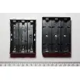 2S Li-ion pack 7.4 V + switch + 15 A fuse× 1Buy
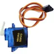 6 V 10 A converter (servo bus)₹126× 1Buy
- 5 V 3 A converter (ESP32)₹518× 1Buy
Kit for this projectPrice on request
Get the kitWiring
PowerGroundSignal
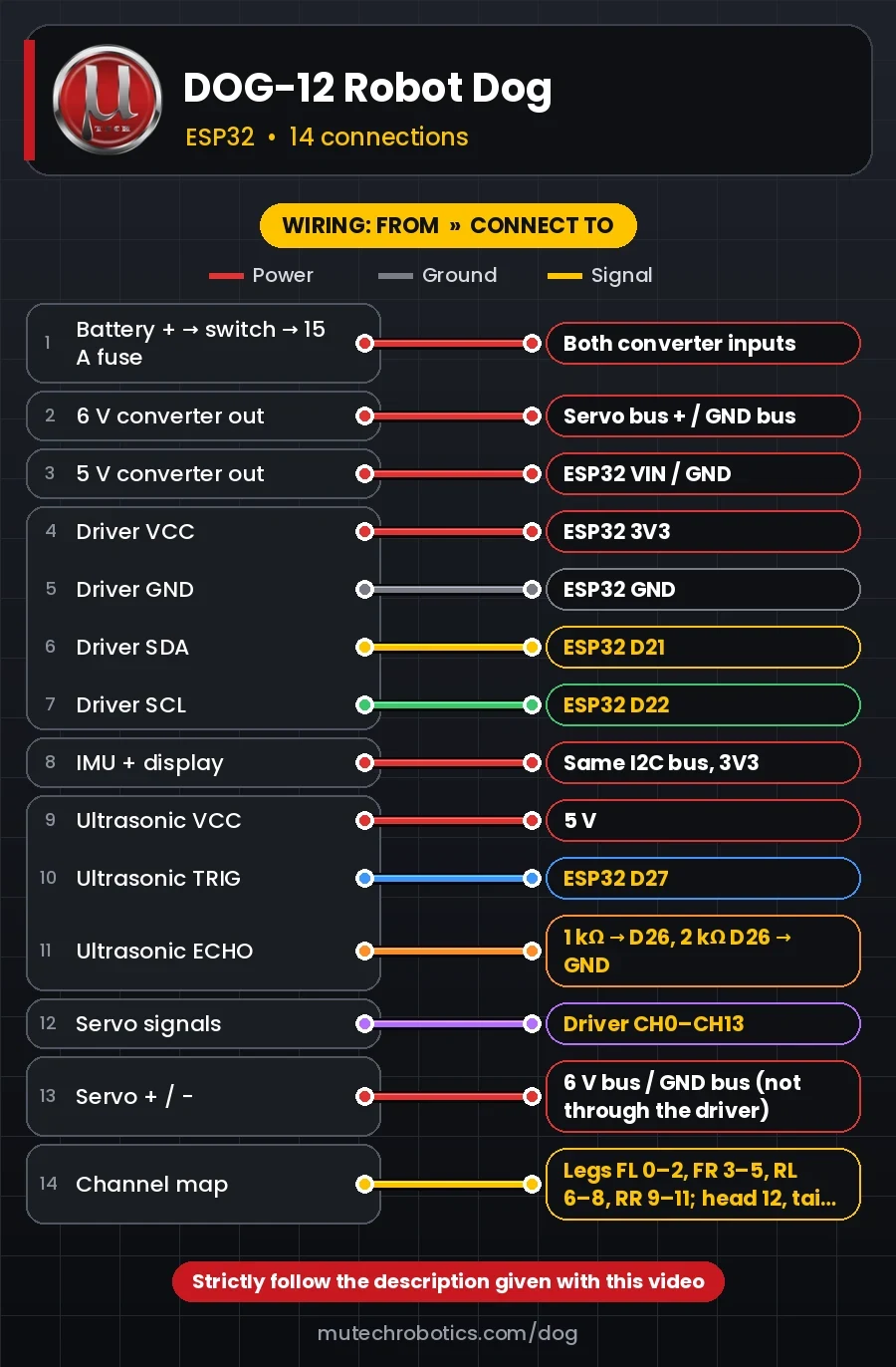
| # | From | Connect to |
|---|---|---|
| 1 Power | Battery + → switch → 15 A fuse | Both converter inputs |
| 2 Power | 6 V converter out | Servo bus + / GND bus |
| 3 Power | 5 V converter out | ESP32 VIN / GND |
| 4 Power | Driver VCC | ESP32 3V3 |
| 5 Ground | Driver GND | ESP32 GND |
| 6 Signal | Driver SDA | ESP32 D21 |
| 7 Signal | Driver SCL | ESP32 D22 |
| 8 Power | IMU + display | Same I2C bus, 3V3 |
| 9 Power | Ultrasonic VCC | 5 V |
| 10 Signal | Ultrasonic TRIG | ESP32 D27 |
| 11 Signal | Ultrasonic ECHO | 1 kΩ → D26, 2 kΩ D26 → GND |
| 12 Signal | Servo signals | Driver CH0–CH13 |
| 13 Power | Servo + / − | 6 V bus / GND bus (not through the driver) |
| 14 Signal | Channel map | Legs FL 0–2, FR 3–5, RL 6–8, RR 9–11; head 12, tail 13 |