
Adults onlyZigbee MCULevel 3/3
Zigbee Smart Street Light Controller
One small node per street light: the nodes form a mesh, so one command switches or dims a whole street, and each node reports lamp faults.
Sign in to save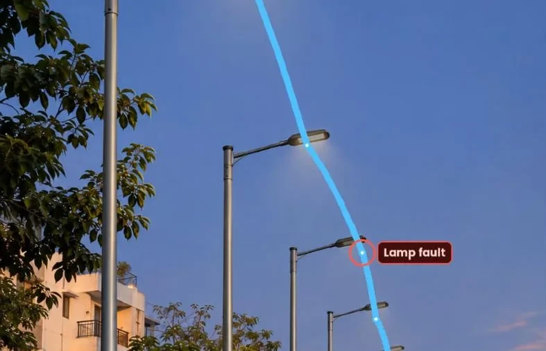
Adults only
It is wired to 230V mains.
Not for children. Build at your own risk.
Keep the mains side in a sealed enclosure and get it wired by a qualified electrician. Not for children.
Strictly follow the description given with this video.
Video
How it works
- Each light gets a Zigbee node; every node passes the signal on to the next, so the whole street forms a mesh.
- If one pole drops out, the signal routes around it through the next pole.
- One command from the phone or gateway switches or dims a whole zone at the same moment.
- A CT clamp and a shunt on the metering module measure the lamp current. If a lamp fails while its relay is ON, the current drops to zero and a fault is raised.
Parts you need
- Zigbee microcontroller board× 1
- AC-DC power module, 230 V to 5 V× 1
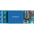 Relay module, 1-channel₹57× 1Buy
- Energy-metering module with shunt× 1
- Split-core CT clamp× 1
- LED street-light driver + lamp× 1
Wiring
PowerGroundSignal
| # | From | Connect to |
|---|---|---|
| 1 Power | AC L / N | AC-DC module input |
| 2 Power | AC-DC module +5V | Zigbee board 5V, relay VCC, meter VCC |
| 3 Ground | AC-DC module GND | Common GND |
| 4 Signal | Zigbee board GPIO | Relay IN |
| 5 Signal | Zigbee board TX / RX | Meter RX / TX |
| 6 Power | AC live | Relay COM |
| 7 Power | Relay NO | LED driver L |
| 8 Ground | AC neutral | LED driver N |
| 9 Signal | CT clamp (around the live to the driver) | Meter CT input |
| 10 Signal | Meter shunt | In series with the lamp load |
3D print files
This project has no 3D-printed parts.
Code
The tested Arduino / ESP32 code for this project will be posted here, ready to copy.